
Why use the Hecken Matching Section?
Three reasons:
- No discontinuities at the start and end points of the section.
- A smooth taper without steps in the section.
- Simple to implement.
How to Implement the Hecken Matching Section
- Define the start impedance, the end impedance, the minimum return loss requirement, and the lowest frequency of operation.
- From those parameters find the ripple parameter, the maximum ripple, and the minimum matching section taper length.
- Then from the table given in Reference 1 below or by recursively calculating as in Reference 2 below, obtain the transcendental function at locations along the matching section.
- Once the transcendental function is known at specific locations along the matching section, directly calculate the impedance at those locations using the value of the function, the start impedance, and the end impedance values.
Once you have obtained the desired matching section impedance profile it is a simple matter to convert those values into the desired transmission line type such as microstrip, coplanar waveguide, coax, or even something like Reference 3.
A Hecken Matching Section Example
Following are excerpts of the process applied to a coaxial cable matching section. A small Visual Basic routine in Microsoft Excel calculated the parameters and the results of the taper were calculated using FEKO.
After defining the parameters required to design the taper, the value of the first maximum in the passband was calculated as well as the value of the minimum length of the taper (Figure 1 cells C9 and C12, respectively).

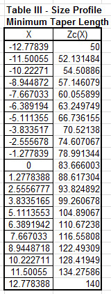
These values were then used to determine the values of the transcendental function along the length of the taper by using Table 1. (Values between rows are interpolated to find the desired values.)

With the values of the transcendental function known, the values of impedance along the taper were calculated directly and scaled to the proper length for the bandwidth desired as shown in Figure 2.
These values can then be converted into the profile of the transmission line type that you are interested in matching. In this example, a coaxial cable profile was used with the values given in Figure 3.
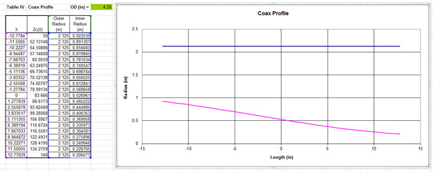
The radius information for the taper is then modeled using FEKO. The resulting geometry is shown in Figure 4.

In this case the taper’s impedance change was defined by changing the radius of the inner conductor only. Notice that it is a continuously smooth curve and there are no abrupt changes or impedance discontinuities.
You can accomplish this in FEKO by saving the points defining the curve in a .csv text file using Microsoft Excel, and then directly importing the values into the spline curve geometry function. The curve is spun, creating a solid geometry part.
The input and output points of the taper are exactly the radius values required to give 50 ohms and 140 ohms. So when connecting this taper profile to coaxial transmission lines (50 ohms and 140 ohms) there will be no discontinuity between the sections.
After meshing the geometry, defining the model parameters, the simulation is ready to run. The resulting return loss for this design is shown in Figure 5.

The modeled response of the taper met the goal values.
The Smith Chart is shown in Figure 6.

In summary, the Hecken taper profile was calculated based on the desired response. The taper was then applied to the desired transmission line topography and the geometry was created in FEKO. The matching section was simulated with the output response meeting all goals.
References
- “A Near-Optimum Matching Section Without Discontinuities”
Rudolf P. Hecken
IEEE Transactions on Microwave Theory and Techniques, Vol. MTT-20 No. 11, November 1972 - “Computation of the Hecken Impedance Function”
J.H. Cloete
IEEE Transactions on Microwave Theory and Techniques, May 1977 - “Design of a Broadband Impedance Matching Section for Peripherally Fed Helical Antennas”
Dirk E. Baker
The 1980 Antenna Applications Symposium, University of Illinois, Allerton Park
Monticello, Illinois, September 1980

You must be logged in to post a comment.