In the last article we looked at the characteristics of a small loop antenna, as well as some of the differences between it and a classical small loop antenna with a uniform current distribution. This article looks at what happens when you take that small loop and put it in close proximity to a ground plane — a common installation.
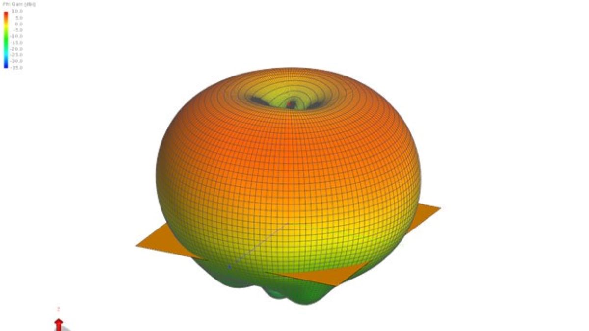
In this case we have a loop 1” in front of a ground plane that is sized at 48” x 48” (large relative to the loop size). The following figures show what happens when the loop is positioned in such a manner. (You can directly compare these patterns to the patterns given in the previous article.)
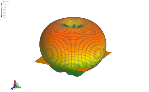
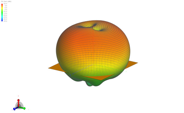
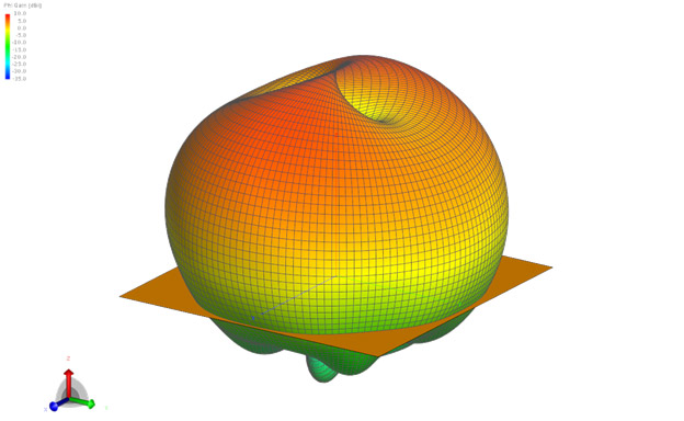
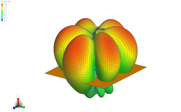
As can be seen, the plate/reflector reduces the gain on the backside, and therefore increases the gain on the front side. With the spacing between the loop and the plate this small relative to the wavelength, the general pattern structure remains relatively intact when compared to the loop without the ground.
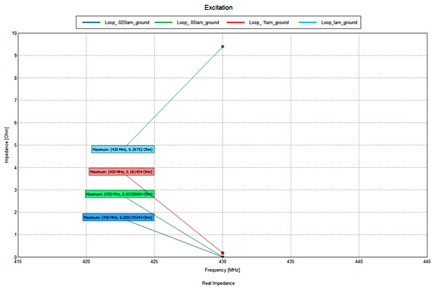
Looking at Figure 5, you will see the big change that occurs when placing the loop close to the ground plane. Comparing the results directly to Figure 5 in the previous article you will notice a significant drop in the real part of the impedance.
For example, when the loop diameter is equal to λ, in the configuration without the plate, the resistance is 1.1K ohm. Once the loop is placed 1” in front of the plate, the resistance drops to 9.4 ohms — a very large drop.
A similar result occurs at the other loop diameters. This drop may make it difficult to match an antenna depending on distance to the ground and the size of the loop — something that should be kept in mind when developing installations.
Overall, the potential ramifications of moving a loop close to a ground plane will need to be weighed on a case-by-case basis.
Lower resistance (being close to the ground plane) causes the Q of the antenna to go up, and therefore, the bandwidth of the antenna to go down.

You must be logged in to post a comment.