Need a really good circularly-polarized (CP) axial ratio for an array of antennas? A technique known as sequential rotation can help achieve this goal, even in large-bandwidth applications. While commonly used with microstrip patch antennas, the sequential rotation technique is by no means limited solely to that application.
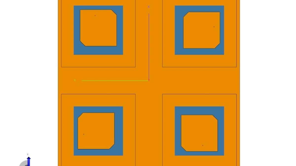
Basic antenna arrays consist of a number of antennas, all aligned in the same direction, as shown in Figure 1.
As you can see, the antennas are not perfectly square. The antennas all face the same direction with the clipped corners pointing toward the upper right and the lower left.
In a sequentially rotated array, instead of the antennas facing the same direction, they rotate around their centers. The question then becomes, what do you gain by doing this?
Why Use Sequential Rotation?
Axial ratio measures the purity of CP. The lower the axial ratio, the better the CP. Sequential rotation improves circular polarization by ensuring that cross-polarized signal components cancel each other out. By making sure these undesirable signals are no longer aligned with one another, the quantity of the imperfections radiated by the array is reduced. The result is an increase in performance.
Implementing Sequential Rotation
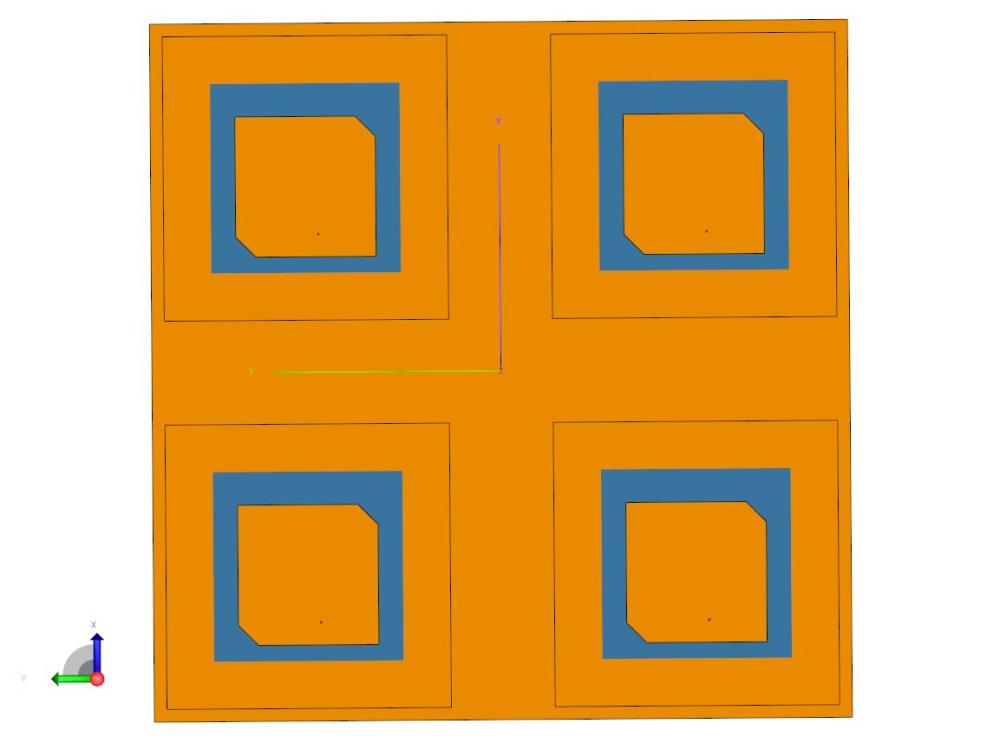
To sequentially rotate an array, each antenna in an array is physically rotated 90 degrees from the last one, as shown in Figure 2 (360 degrees divided by four antennas).
In an application with six antennas, each antenna would be rotated 60 degrees relative to the last one (360 degrees divided by 6 antennas). With an array of many antennas you might break the problem down into blocks of sequentially rotated antennas, instead of implementing sequential rotation across the entire array.
Physically rotating the antennas is the first step. For sequential rotation to work, the input phase must be shifted for each antenna, as well. Again looking at Figure 2, if the upper-left antenna is 0 degrees phase angle, the signal phase for the upper-right antenna will be 90 degrees out of phase from the upper-left antenna, and so on for each antenna in the array.
The obvious downside of sequential rotation is complexity. The circuitry feeding the antenna array becomes more involved because of the extra components or space required to achieve the electrical phase-shifting throughout the array. However, the complexity is frequently outweighed by the increase in performance.
Example of Sequential Rotation Performance
As mentioned before, Figure 1 shows an example of a standard CP non-rotated array. All of the ports are in the same physical orientation, and all four of the array elements see the same electrical input phase (0 degrees, in this case).
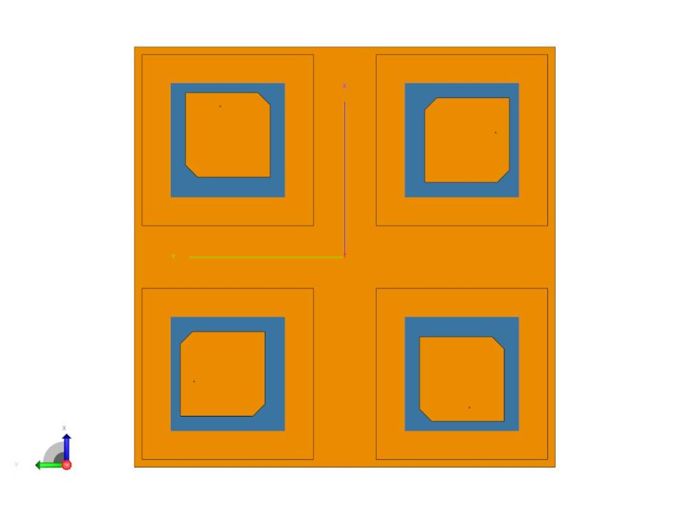
Figure 3 shows the sequentially rotated array with each element in the array rotated 90 degrees from the last to achieve right-hand circular polarization (RHCP):

- The port phase used for the element in the lower-right corner is 0 degrees.
- The port phase used in the upper-right corner is -90 degrees.
- The port phase for the upper-left corner is -180 degrees.
- The port phase for the lower-left corner is -270 degrees.
RHCP is significantly improved over the mediocre performance of the non-rotated array of elements shown in Figure 2.
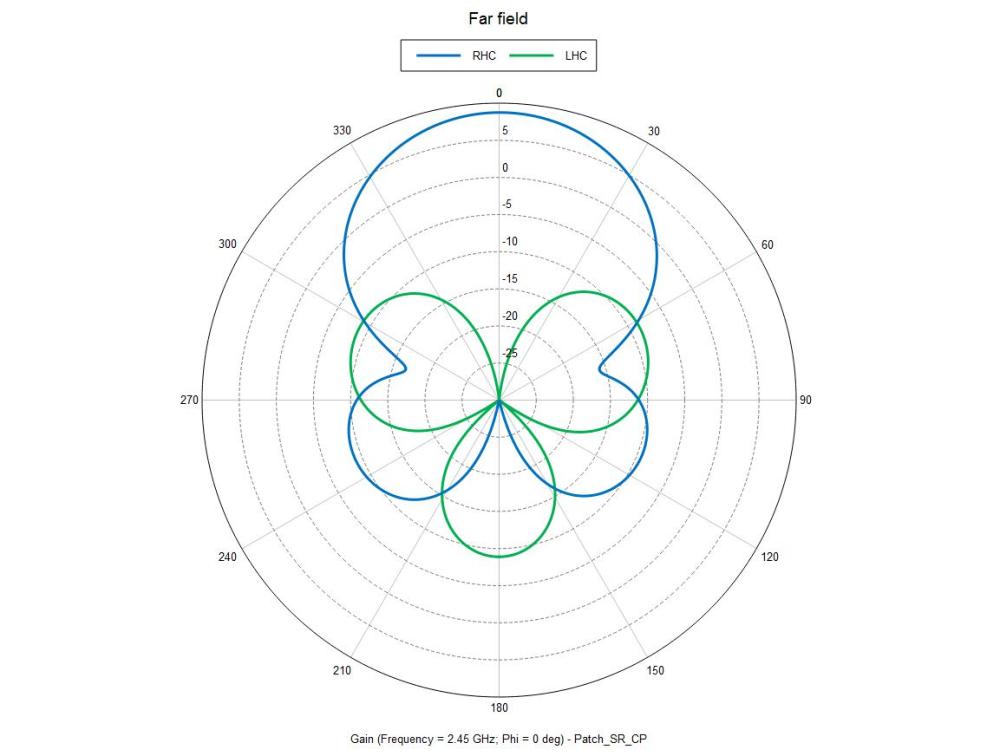
Figures 4 and 5 show the antenna patterns (phi = 0) for the non-sequentially rotated array. You can see in Figure 4 that in this case the LHCP component is only down from the RHCP component by 8 to 9 dB at the beam peak.
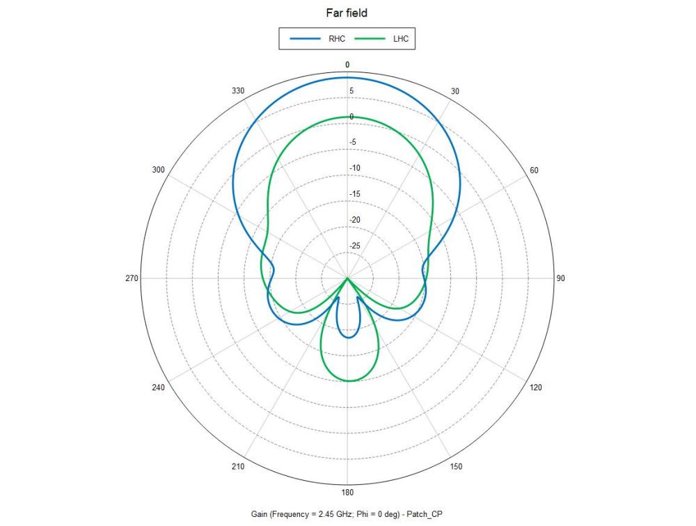
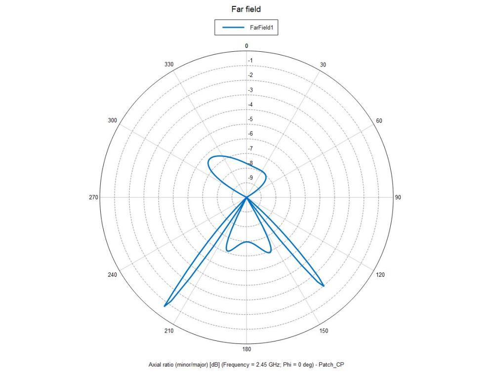
This means that the axial ratio is not very good, coming in at around -8 dB, as can be seen in Figure 5. (No effort has been made to improve the gain.)
Figures 6 and 7 show the antenna patterns (phi = 0) for the sequentially rotated array.

By using only sequential rotation, the performance went from mediocre to exceptional.
Final Thoughts
- Sequential rotation can be used on an antenna array of any number of elements.
- Larger arrays can be broken down into blocks of sequentially rotated antennas.
- Circular arrays can use different rotation angles and phases on different radii.
- Circular polarization can be achieved by sequentially rotating even linearly polarized elements.
- If in the sequence of rotation an array does not lend itself to a perfect linear rotation, a partially rotated sequence can still provide better CP in many cases.
- If you have a multi-feed patch, the phase progression applies to all of the ports on a given patch. For instance, if the third patch has two ports, and the third patch is to receive a 180-degree phase shift, then both ports on that patch will need to receive the 180-degree phase shift.
- Sequential rotation works in a beam steering array.
For further guidance on sequential rotation, see Modern Antenna Handbook by Constantine Balanis where you will find the topic covered in the section on microstrip antennas.

You must be logged in to post a comment.