In the course of our work, some questions came up regarding the impedance and antenna patterns of small loop antennas — and not so small loops.
If you start with the trusted antenna book of your choice, in many cases you will find antenna patterns for small loop antennas using a uniform current distribution when calculating the far-field patterns.
Have you ever wondered how this differs from non-uniform current distributions (which will typically be the case)?
Evaluating Small Loop Antennas with Non-Uniform Current Distributions
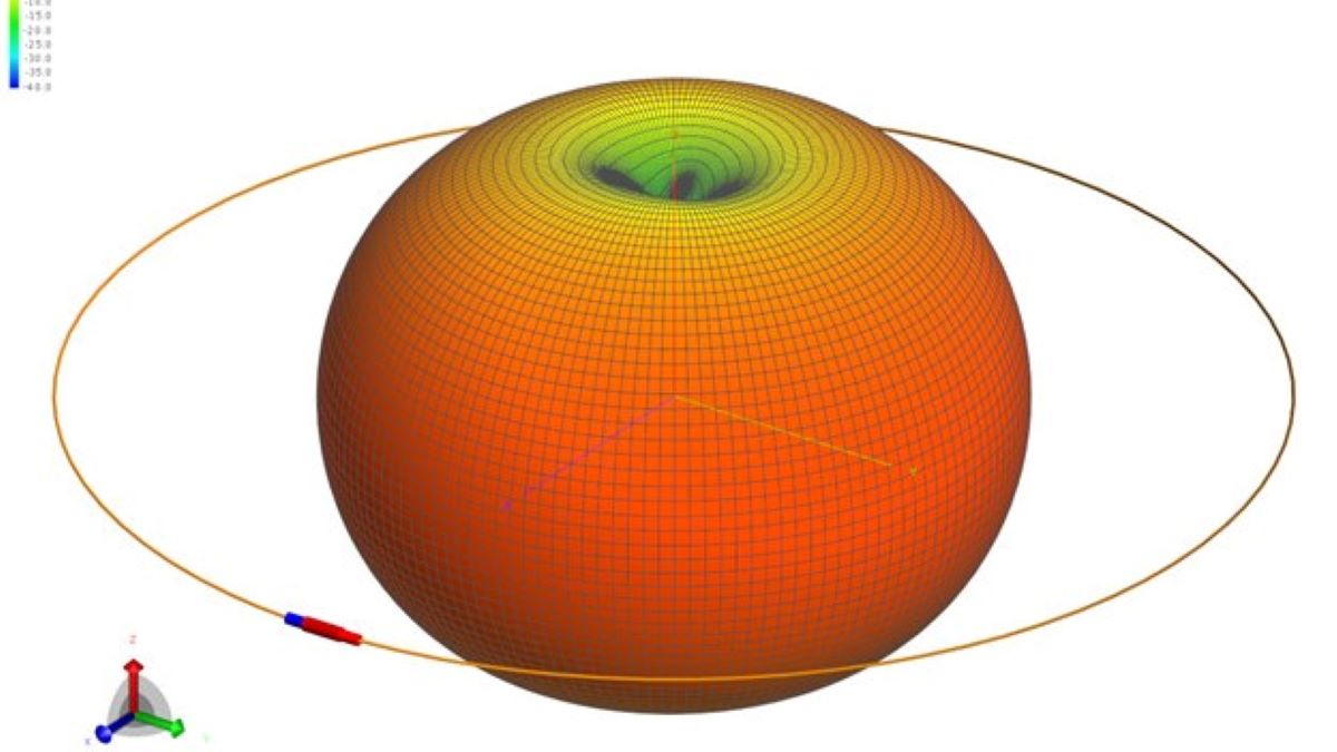
Using FEKO, I ran simulations for several different diameters. The following images show the 3D antenna patterns for several loop diameters:
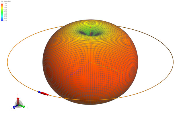
Figure 1 shows the typical doughnut-shaped antenna pattern for a very small loop. That doughnut shape is also typically shown up to a radius of λ/10.
Now it starts to get interesting. You can see that we are already diverging from the classic doughnut shape at a diameter of only λ/20.

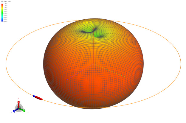
By λ/10 there are dual nulls at the top and bottom of the 3D pattern.
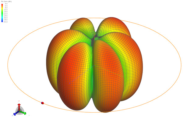
And finally at a diameter of λ we end up with a lobed orange slice antenna pattern, or in other words, an antenna pattern that is not rotationally symmetric around the Z-axis such as would be produced with a uniform current distribution on the wire.
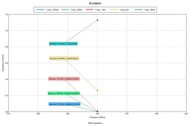
As you would expect, the real part of the impedance is increasing as the diameter increases.
So overall there is a fairly significant difference between the classic uniform current antenna pattern and the real world simple loop antenna.
Next we will take a look at how the loop antenna performs in close proximity to a ground plane in terms of antenna pattern and impedance.

You must be logged in to post a comment.