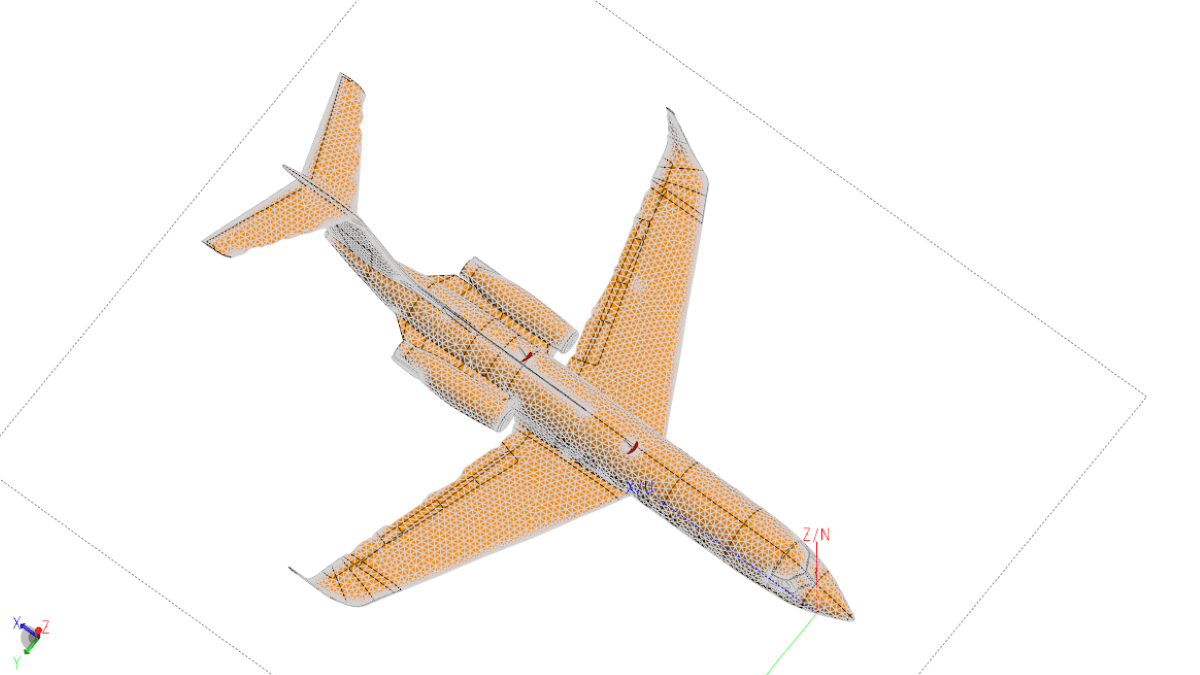
For electrically large structures over a broad bandwidth, the FEKO grid search optimizer can be used to dynamically create a mesh. In this example, we will model a VHF antenna on a Gulfstream VI aircraft over the frequency range of 100MHz to 600MHz with an increment of 101 points.
There are many ways of doing this but as you will quickly realize, given the size of the aircraft and the frequency range, to mesh the aircraft to support the highest frequency and then run the entire range in one frequency sweep using the standard FEKO solvers will require a great deal of system resources. Figures 1 and 2 show the huge difference in the number of elements required to obtain a quality mesh at the respective frequencies.

Antenna and aircraft models courtesy VStar Systems, Inc.

Antenna and aircraft models courtesy VStar Systems, Inc.
At 100MHz approximately 65,000 triangles are needed; but at 600MHz nearly ten times as many are required. Running the entire sweep as described above will be a significantly slower process than running a sweep where each frequency has its own unique mesh determined by how many triangles are needed for that individual frequency. Meshing for each individual frequency allows the demand on resources to be reduced while still acquiring representative data.
Creating a Mesh for Each Frequency
While running and meshing each frequency individually and then combining the results is possible, the operation would become a bit tedious if there were many points involved.
The good news is that there is a better way: Set up the grid optimizer in FEKO so that it steps through the number of desired points over the desired span. Then let the optimizer generate the mesh and run each step in the solver. Using the grid optimizer reduces the demand on system resources, while freeing the user from manually setting up and running each frequency.
Setting Up the Grid Optimizer
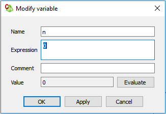
Step 1
Create the stepping variable — n in the example shown in Figure 3.
Step 2
Create the variable that relates the step increment (n) to the actual simulation frequency. Figure 4 shows an example of a geometric step that covers the range.
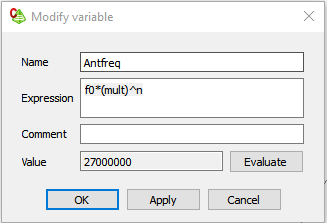
This variable, relating the stepping variable to the simulation frequency, can be linear, logarithmic, or whatever else you might choose based on frequency and sampling requirements.
Step 3
Set the solution frequency to the variable created or the value entered under “Expression” as shown in Figure 5.

Step 4
Set up the optimizer. The optimizer is looking for a goal so that it can zero in on a target data point that best matches that goal. However, in this case the goal is irrelevant; we are only using the optimizer to step through the frequencies. Therefore, although the goal will still need be entered so that the optimizer will run, the actual value is unimportant. Figure 6 shows our “dummy goal.”

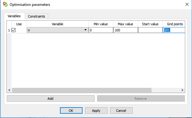
Step 5
Enter the stepping parameter (n from above) into the Parameter window, as shown in Figure 7.
Step 6
Finally, but most importantly, MAKE SURE THAT THE “Delete all files (except optimum)” CHECKBOX IS NOT SELECTED as shown in Figure 8.

If this checkbox is selected, all of the interim optimization files will be deleted.
Final Notes
Given the size of the mesh for the aircraft model it is quite apparent that the straight MoM solver will never work at higher frequencies. At these frequencies, you will most certainly be using the Multi-Level Fast Multipole Method (MLFMM) or some other related technique to reduce both the time and the complexity of the solution even further.
Another trick that can help reduce time and system requirements is to mesh the entire aircraft using a coarser mesh, while adding a tighter refinement mesh around the antenna itself. This mesh can be tied to the wavelength and, therefore, the step increment (n) mentioned above.
No matter which method is used, it is always a good idea to make several validation runs at specific frequencies across the desired frequency range to ensure that the mesh generated at each frequency by the solver is adequate.

You must be logged in to post a comment.